
- MENU
- Home
-
Categories
- Air conditioner (switchgear cabinet)
- Base/base element (switchgear cabinet)
- Case for component installation with modular spacing 19 inch
- Climate control door (enclosure/cabinet)
- Climate control side panel (enclosure/cabinet)
- Component for arrangement / baying system (switchgear cabinet)
- View all categories
- Accessories/spare parts for domestic switching devices
- Accessories/spare parts for socket outlets/plugs with protective contact
- Cable entry
- Combination of switch/push button with socket outlet
- Control element/cover plate for domestic switching devices
- Controller for light controlling system
- View all categories
- Accessories/spare parts for earthing and lightning
- Accessories/spare parts for surge protection data networks/MCR-technology
- Accessories/spare parts for surge protection power supply systems
- Air-termination equipment for lightning protection
- Base for air termination systems lightning protection
- Basic element for surge protection device
- View all categories
- AC-power supply
- Accessories/spare parts for command devices
- Accessories/spare parts for electronic motor control and protection device
- Accessories/spare parts for emergency stop pull cord switch
- Accessories/spare parts for frequency controller
- Accessories/spare parts for low-voltage switch technology
- View all categories
- Accessories/spare parts for underfloor installation ducting systems
- Bend for underfloor installation ducting systems
- Coupler for underfloor installation duct
- Cover for underfloor installation duct flush floor open
- Cover plate for installation units
- End piece for underfloor installation duct
- View all categories
- Request Quote
- How RFQ Works
- Contact Us
- FAQ
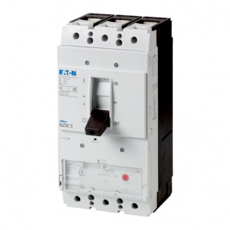 View larger
Images are for illustrative purposes only. Please refer to data sheet for details
NZMC3-S320 109677 Y7-109677 EATON ELECTRIC NZM Auto Int., 4P, 320A
NZMC3-S320
109677
Y7-109677
EATON - MOELLER
1 Pcs.
NZM Auto Int., 4P, 320A
NZMC3-S320
Eaton Moeller series NZM - Molded Case Circuit Breaker. Circuit-breaker, 3p, 320A, busbar terminal for CU C, frame 3, S320
Circuit-breaker NZM3, 3 pole, Switching capacity 400/415 V 50 Hz( Icu ): 36 kA, Rated current = rated uninterrupted current( In = Iu ): 320 A, Installation type: Fixed, Screw connection, Standard/Approval: IEC, Protective function: Short-circuit protection
Automation > Power circuit-breaker for trafo/generator/installation protection
Circuit Breakers NZM
Product condition, packaging, certifications and applicable manufacturer warranty terms are confirmed with the quotation.
More info
▲General specifications
| Product Name | Eaton Moeller series NZM molded case circuit breaker magnetic |
| Catalog Number | 109677 |
| Model Code | NZMC3-S320 |
| EAN | 4015081092635 |
| Product Length/Depth | 166 mm |
| Product Height | 275 mm |
| Product Width | 140 mm |
| Product Weight | 5.8 kg |
| Compliances | RoHS conform |
| Certifications | IEC/EN 60947 IEC |
Delivery program
| Application | Use in unearthed supply systems at 690 V |
| Type | Circuit breaker |
| Circuit breaker frame type | NZM3 |
| Number of poles | Three-pole |
| Amperage Rating | 320 A |
| Release system | Thermomagnetic release |
| Special features |
|
Technical Data - Electrical
| Voltage rating | 690 V - 690 V |
| Rated operational current | 279 A (400 V AC-3, making and breaking capacity) |
| Amperage Rating | 320 A |
| Short-circuit total breaktime | < 10 ms |
| Electrical connection type of main circuit | Screw connection |
| Isolation | 300 V AC (between the auxiliary contacts) 500 V AC (between auxiliary contacts and main contacts) |
| Utilization category | A (IEC/EN 60947-2) |
| Overvoltage category | III |
| Pollution degree | 3 |
| Lifespan, electrical | 2000 operations at 400 V AC-3 5000 operations at 400 V AC-1 2000 operations at 690 V AC-3 3000 operations at 690 V AC-1 2000 operations at 415 V AC-3 |
| Direction of incoming supply | As required |
Technical Data - Mechanical
| Mounting Method | Built-in device fixed built-in technique Fixed |
| Mounting Method | Built-in device fixed built-in technique Fixed |
| Degree of protection | IP20 (basic degree of protection, in the operating controls area) IP20 |
| Degree of protection (IP), front side | IP40 (with insulating surround) IP66 (with door coupling rotary handle) |
| Degree of protection (terminations) | IP10 (tunnel terminal) IP00 (terminations, phase isolator and strip terminal) |
| Shock resistance | 20 g (half-sinusoidal shock 20 ms) |
| Climatic proofing | Damp heat, cyclic, to IEC 60068-2-30 Damp heat, constant, to IEC 60068-2-78 |
| Special features |
|
| Lifespan, mechanical | 15000 operations |
Technical Data - Mechanical - Terminals
| Terminal capacity (control cable) | 0.75 mm² - 2.5 mm² (1x) 0.75 mm² - 1.5 mm² (2x) |
| Terminal capacity (copper busbar) | M10 at rear-side screw connection Min. 20 mm x 5 mm direct at switch rear-side connection Max. 30 mm x 10 mm + 30 mm x 5 mm direct at switch rear-side connection Max. 10 mm x 50 mm (2x) at rear-side width extension |
| Terminal capacity (copper solid conductor/cable) | 300 mm² (2x) at rear-side width extension 16 mm² (1x) at tunnel terminal 16 mm² (1x) direct at switch rear-side connection 16 mm² (2x) at box terminal 16 mm² (2x) direct at switch rear-side connection |
| Terminal capacity (copper stranded conductor/cable) | 25 mm² - 240 mm² (1x) direct at switch rear-side connection 35 mm² - 240 mm² (1x) at box terminal 16 mm² - 185 mm² (1x) at 1-hole tunnel terminal 25 mm² - 120 mm² (2x) at box terminal 25 mm² - 240 mm² (2x) direct at switch rear-side connection |
| Terminal capacity (copper strip) | 10 segments of 50 mm x 1 mm (2x) at rear-side width extension Max. 10 segments of 24 mm x 1 mm + 5 segments of 24 mm x 1 mm Max. 10 segments of 32 mm x 1 mm + 5 segments of 32 mm x 1 mm at rear-side connection (punched) Min. 6 segments of 16 mm x 0.8 mm at box terminal Min. 6 segments of 16 mm x 0.8 mm at rear-side connection (punched) Max. 8 segments of 24 mm x 1 mm (2x) at box terminal |
Design verification as per IEC/EN 61439 - technical data
| Equipment heat dissipation, current-dependent | 78.64 W |
Design verification as per IEC/EN 61439
| 10.2.2 Corrosion resistance | Meets the product standard's requirements. |
| 10.2.3.1 Verification of thermal stability of enclosures | Meets the product standard's requirements. |
| 10.2.3.2 Verification of resistance of insulating materials to normal heat | Meets the product standard's requirements. |
| 10.2.3.3 Resist. of insul. mat. to abnormal heat/fire by internal elect. effects | Meets the product standard's requirements. |
| 10.2.4 Resistance to ultra-violet (UV) radiation | Meets the product standard's requirements. |
| 10.2.5 Lifting | Does not apply, since the entire switchgear needs to be evaluated. |
| 10.2.6 Mechanical impact | Does not apply, since the entire switchgear needs to be evaluated. |
| 10.2.7 Inscriptions | Meets the product standard's requirements. |
| 10.3 Degree of protection of assemblies | Does not apply, since the entire switchgear needs to be evaluated. |
| 10.4 Clearances and creepage distances | Meets the product standard's requirements. |
| 10.5 Protection against electric shock | Does not apply, since the entire switchgear needs to be evaluated. |
| 10.6 Incorporation of switching devices and components | Does not apply, since the entire switchgear needs to be evaluated. |
| 10.7 Internal electrical circuits and connections | Is the panel builder's responsibility. |
| 10.8 Connections for external conductors | Is the panel builder's responsibility. |
| 10.9.2 Power-frequency electric strength | Is the panel builder's responsibility. |
| 10.9.3 Impulse withstand voltage | Is the panel builder's responsibility. |
| 10.9.4 Testing of enclosures made of insulating material | Is the panel builder's responsibility. |
| 10.10 Temperature rise | The panel builder is responsible for the temperature rise calculation. Eaton will provide heat dissipation data for the devices. |
| 10.11 Short-circuit rating | Is the panel builder's responsibility. The specifications for the switchgear must be observed. |
| 10.12 Electromagnetic compatibility | Is the panel builder's responsibility. The specifications for the switchgear must be observed. |
| 10.13 Mechanical function | The device meets the requirements, provided the information in the instruction leaflet (IL) is observed. |
Additional information
| Functions | Short-circuit protection |
| Feature Name | Feature Value |
|---|---|
| Rated permanent current Iu (EF001389) | 320 A |
| Rated voltage (EF003977) | 690 V |
| Rated short-circuit breaking capacity Icu at 400 V, 50 Hz (EF007048) | 36 kA |
| Overload release current setting (EF002336) | 0 A |
| Adjustment range short-term delayed short-circuit release (EF007129) | 0 A |
| Adjustment range undelayed short-circuit release (EF007131) | 2560 A |
| Device construction (EF008240) | Built-in device fixed built-in technique |
| Integrated earth fault protection (EF007296) | No |
| Type of electrical connection of main circuit (EF006819) | Screw connection |
| Suitable for DIN rail (top hat rail) mounting (EF007250) | No |
| DIN rail (top hat rail) mounting optional (EF008904) | No |
| Number of auxiliary contacts as normally closed contact (EF001377) | 0 |
| Number of auxiliary contacts as normally open contact (EF001376) | 0 |
| Number of auxiliary contacts as change-over contact (EF003531) | 0 |
| With switched-off indicator (EF007006) | No |
| With integrated under voltage release (EF001390) | No |
| Number of poles (EF001391) | 3 |
| Position of connection for main current circuit (EF006671) | Front |
| Type of control element (EF006976) | Rocker lever |
| Complete device with protection unit (EF008906) | Yes |
| Motor drive integrated (EF006697) | No |
| Motor drive optional (EF007386) | Yes |
| Degree of protection (IP) (EF005474) | IP20 |