
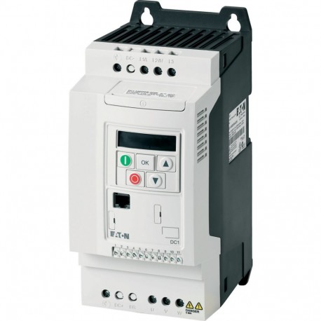
 View larger
Images are for illustrative purposes only. Please refer to data sheet for details
DC1-12011FB-A20N 169252 EATON ELECTRIC Variable Frequency Drive, 1-/3- 230 V, 10.5 A, 2.2 kW, EMC-Filter, Br..
DC1-12011FB-A20N
169252
EATON - MOELLER
1 Pcs.
Variable Frequency Drive, 1-/3- 230 V, 10.5 A, 2.2 kW, EMC-Filter, Brake-Chopper
Variable frequency drive, Part group reference (e.g. DIL): DC1, Rated operational voltage: Ue = 230 V AC, 1-phase, 240 V AC, single-phase, Output voltage with Ve: U2 = 230 V AC, 3-phase, 240 V AC, 3-phase, Mains voltage (50/60Hz): ULN = 200 (-10%) - 240 (+10%) V, Rated operational current At 150% overload: Ie = 10.5 A, Note: Rated operational current at an operating frequency of 16 kHz and an ambient air temperature of +50 °C, Note: Overload cycle for 60 s every 600 s, Assigned motor rating Note: for normal internally and externally ventilated 4 pole, three-phase asynchronous motors with 1500 rpm-1 at 50 Hz or 1800 min-1 at 60 Hz , Overload cycle for 60 s every 600 s, at 230 V, 50 Hz, Assigned motor rating 150 % Overload: P = 2.2 kW, 150 % Overload: IM = 8.7 A, Assigned motor rating Note: at 220 - 240 V, 60 Hz, Assigned motor rating 150 % Overload: P = 3 HP, Assigned motor rating 150 % Overload: IM = 9.6 A, Degree of Protection: IP20/NEMA 0, Interface/field bus (built-in): OP-Bus (RS485)/Modbus RTU, CANopen®, Fieldbus connection (optional): SmartWire-DT, Fitted with: Radio interference suppression filter, Brake chopper, 7-digital display assembly, Frame size: FS2, Connection to SmartWire-DT: with SmartWire-DT module DX-NET-SWD3 , Standards: Specification for general requirements: IEC/EN 61800-2, EMC requirements: IEC/EN 61800-3, Safety requirements: IEC/EN 61800-5-1
Automation > Frequency converter less than 1 kV
Power XL Frequency Converters
Product condition, packaging, certifications and applicable manufacturer warranty terms are confirmed with the quotation.
More info
▲Delivery programme
Product range | Variable frequency drives | ||
Part group reference (e.g. DIL) | DC1 | ||
Rated operational voltage | Ue | 230 V AC, 1-phase 240 V AC, single-phase | |
Output voltage with Ve | U2 | 230 V AC, 3-phase 240 V AC, 3-phase | |
Mains voltage (50/60Hz) | ULN | V | 200 (-10%) - 240 (+10%) |
Rated operational current | |||
At 150% overload | Ie | A | 10.5 |
Note | Rated operational current at an operating frequency of 16 kHz and an ambient air temperature of +50 °C | ||
Note | Overload cycle for 60 s every 600 s | ||
Assigned motor rating | |||
Note | for normal internally and externally ventilated 4 pole, three-phase asynchronous motors with 1500 rpm-1at 50 Hz or 1800 min-1at 60 Hz | ||
Note | Overload cycle for 60 s every 600 s | ||
Note | at 230 V, 50 Hz | ||
150 % Overload | P | kW | 2.2 |
150 % Overload | IM | A | 8.7 |
Note | at 220 - 240 V, 60 Hz | ||
150 % Overload | P | HP | 3 |
150 % Overload | IM | A | 9.6 |
Degree of Protection | IP20/NEMA 0 | ||
Interface/field bus (built-in) | OP-Bus (RS485)/Modbus RTU, CANopen® | ||
Fieldbus connection (optional) | SmartWire-DT | ||
Fitted with | Radio interference suppression filter Brake chopper 7-digital display assembly | ||
Frame size | FS2 | ||
Connection to SmartWire-DT | with SmartWire-DT module DX-NET-SWD3 |
Technical data
| General | |||
Standards | Specification for general requirements: IEC/EN 61800-2 EMC requirements: IEC/EN 61800-3 Safety requirements: IEC/EN 61800-5-1 | ||
Certifications | CE, UL, cUL, c-Tick, Ukr Sepro, EAC | ||
Production quality | RoHS, ISO 9001 | ||
Climatic proofing | ρw | % | < 95%, average relative humidity (RH), non-condensing, non-corrosive |
Ambient temperature | |||
operation (150 % overload) | ϑ | °C | -10 - +50 |
| -10 - +45 °C for UL compliance over a period of 24 hours. | |||
Storage | ϑ | °C | -40 - +60 |
Radio interference level | |||
Radio interference class (EMC) | C1, C2, C3, depending on the motor cable length, the connected load, and ambient conditions. External radio interference suppression filters (optional) may be necessary. | ||
Environment (EMC) | 1st and 2nd environments | ||
maximum motor cable length | I | m | C1 ≤ 1 m C2 ≤ 5 m C3 ≤ 25 m |
Mounting position | Vertical | ||
Altitude | m | 0 - 1000 m above sea level Above 1000 m: 1% derating for every 100 m max. 4000 m | |
Degree of Protection | IP20/NEMA 0 | ||
Protection against direct contact | BGV A3 (VBG4, finger- and back-of-hand proof) | ||
| Main circuit | |||
Supply | |||
Rated operational voltage | Ue | 230 V AC, 1-phase 240 V AC, single-phase | |
Mains voltage (50/60Hz) | ULN | V | 200 (-10%) - 240 (+10%) |
Input current (150% overload) | ILN | A | 19.5 |
System configuration | AC supply systems with earthed center point | ||
Supply frequency | fLN | Hz | 50/60 |
Frequency range | fLN | Hz | 48 - 62 |
Mains switch-on frequency | Maximum of one time every 30 seconds | ||
Power section | |||
Function | Frequency inverter with internal DC link and IGBT inverter | ||
Overload current (150% overload) | IL | A | 15.75 |
max. starting current (High Overload) | IH | % | 175 |
Note about max. starting current | for 2 seconds every 20 seconds | ||
Output voltage with Ve | U2 | 230 V AC, 3-phase 240 V AC, 3-phase | |
Output Frequency | f2 | Hz | 0 - 50/60 (max. 500) |
Switching frequency | fPWM | kHz | 16 adjustable 4 - 32 (audible) |
Operation Mode | U/f control Speed control with slip compensation | ||
Frequency resolution (setpoint value) | Δf | Hz | 0.1 |
Rated operational current | |||
At 150% overload | Ie | A | 10.5 |
Note | Rated operational current at an operating frequency of 16 kHz and an ambient air temperature of +50 °C | ||
Power loss | |||
Heat dissipation at rated operational current | PV | W | 103.4 |
Efficiency | η | % | 95.3 |
Maximum leakage current to ground (PE) without motor | IPE | mA | 2.49 |
Fitted with | Radio interference suppression filter Brake chopper 7-digital display assembly | ||
Frame size | FS2 | ||
Motor feeder | |||
Note | for normal internally and externally ventilated 4 pole, three-phase asynchronous motors with 1500 rpm-1at 50 Hz or 1800 min-1at 60 Hz | ||
Note | Overload cycle for 60 s every 600 s | ||
Note | at 230 V, 50 Hz | ||
150 % Overload | P | kW | 2.2 |
Note | at 220 - 240 V, 60 Hz | ||
150 % Overload | P | HP | 3 |
maximum permissible cable length | I | m | screened: 100 screened, with motor choke: 200 unscreened: 150 unscreened, with motor choke: 300 |
Apparent power | |||
Apparent power at rated operation 230 V | S | kVA | 4.18 |
Apparent power at rated operation 240 V | S | kVA | 4.36 |
Braking function | |||
Standard braking torque | max. 30 % MN | ||
DC braking torque | adjustable to 100 % | ||
Braking torque with external braking resistance | Max. 100% of rated operational current Iewith external braking resistor | ||
minimum external braking resistance | Rmin | Ω | 47 |
Switch-on threshold for the braking transistor | UDC | V | 390 V DC |
| Control section | |||
Reference voltage | Us | V | 10 V DC (max. 10 mA) |
Analog inputs | 2, parameterizable, 0 - 10 V DC, 0/4 - 20 mA | ||
Analog outputs | 1, parameterizable, 0 - 10 V | ||
Digital inputs | 4, parameterizable, max. 30 V DC | ||
Digital outputs | 1, parameterizable, 24 V DC | ||
Relay outputs | 1, parameterizable, N/O, 6 A (250 V, AC-1) / 5 A (30 V, DC-1) | ||
Interface/field bus (built-in) | OP-Bus (RS485)/Modbus RTU, CANopen® | ||
| Assigned switching and protective elements | |||
Power Wiring | |||
IEC (Type B, gG), 150 % | FAZ-B25/1N | ||
UL (Class CC or J) | A | 25 | |
150 % overload (CT/IH, at 50 °C) | DX-LN1-024 | ||
Motor feeder | |||
150 % overload (CT/IH, at 50 °C) | DX-LM3-011 | ||
150 % overload (CT/IH, at 50 °C) | DX-SIN3-016 | ||
10 % duty factor (DF) | DX-BR050-0K4 | ||
20 % duty factor (DF) | DX-BR050-0K8 | ||
40 % duty factor (DF) | DX-BR047-3K1 | ||
Design verification as per IEC/EN 61439(Show features)(Hide features)
Technical data for design verification | |||
Rated operational current for specified heat dissipation | In | A | 10.5 |
Heat dissipation per pole, current-dependent | Pvid | W | 0 |
Equipment heat dissipation, current-dependent | Pvid | W | 103.4 |
Static heat dissipation, non-current-dependent | Pvs | W | 0 |
Heat dissipation capacity | Pdiss | W | 0 |
Operating ambient temperature min. | °C | -10 | |
Operating ambient temperature max. | °C | 50 | |
IEC/EN 61439 design verification | |||
10.2 Strength of materials and parts | |||
10.2.2 Corrosion resistance | Meets the product standard's requirements. | ||
10.2.3.1 Verification of thermal stability of enclosures | Meets the product standard's requirements. | ||
10.2.3.2 Verification of resistance of insulating materials to normal heat | Meets the product standard's requirements. | ||
10.2.3.3 Verification of resistance of insulating materials to abnormal heat and fire due to internal electric effects | Meets the product standard's requirements. | ||
10.2.4 Resistance to ultra-violet (UV) radiation | Meets the product standard's requirements. | ||
10.2.5 Lifting | Does not apply, since the entire switchgear needs to be evaluated. | ||
10.2.6 Mechanical impact | Does not apply, since the entire switchgear needs to be evaluated. | ||
10.2.7 Inscriptions | Meets the product standard's requirements. | ||
10.3 Degree of protection of ASSEMBLIES | Does not apply, since the entire switchgear needs to be evaluated. | ||
10.4 Clearances and creepage distances | Meets the product standard's requirements. | ||
10.5 Protection against electric shock | Does not apply, since the entire switchgear needs to be evaluated. | ||
10.6 Incorporation of switching devices and components | Does not apply, since the entire switchgear needs to be evaluated. | ||
10.7 Internal electrical circuits and connections | Is the panel builder's responsibility. | ||
10.8 Connections for external conductors | Is the panel builder's responsibility. | ||
10.9 Insulation properties | |||
10.9.2 Power-frequency electric strength | Is the panel builder's responsibility. | ||
10.9.3 Impulse withstand voltage | Is the panel builder's responsibility. | ||
10.9.4 Testing of enclosures made of insulating material | Is the panel builder's responsibility. | ||
10.10 Temperature rise | The panel builder is responsible for the temperature rise calculation. Eaton will provide heat dissipation data for the devices. | ||
10.11 Short-circuit rating | Is the panel builder's responsibility. The specifications for the switchgear must be observed. | ||
10.12 Electromagnetic compatibility | Is the panel builder's responsibility. The specifications for the switchgear must be observed. | ||
10.13 Mechanical function | The device meets the requirements, provided the information in the instruction leaflet (IL) is observed. |
Technical data ETIM 6.0(Show features)(Hide features)
| Low-voltage industrial components (EG000017) / Frequency converter =< 1 kV (EC001857) | |||
| Electric engineering, automation, process control engineering / Electrical drive / Static frequency converter / Static frequency converter = < 1 kv ([email protected] [AKE177011]) | |||
Mains voltage | V | 200 - 240 | |
Mains frequency | 50/60 Hz | ||
Number of phases input | 1 | ||
Number of phases output | 3 | ||
Max. output frequency | Hz | 500 | |
Max. output voltage | V | 230 | |
Rated output current I2N | A | 11 | |
Max. output at quadratic load at rated output voltage | kW | 2.2 | |
Max. output at linear load at rated output voltage | kW | 2.2 | |
With control unit | Yes | ||
Application in industrial area permitted | Yes | ||
Application in domestic- and commercial area permitted | Yes | ||
Supporting protocol for TCP/IP | No | ||
Supporting protocol for PROFIBUS | No | ||
Supporting protocol for CAN | Yes | ||
Supporting protocol for INTERBUS | No | ||
Supporting protocol for ASI | No | ||
Supporting protocol for KNX | No | ||
Supporting protocol for MODBUS | Yes | ||
Supporting protocol for Data-Highway | No | ||
Supporting protocol for DeviceNet | No | ||
Supporting protocol for SUCONET | No | ||
Supporting protocol for LON | No | ||
Supporting protocol for PROFINET IO | No | ||
Supporting protocol for PROFINET CBA | No | ||
Supporting protocol for SERCOS | No | ||
Supporting protocol for Foundation Fieldbus | No | ||
Supporting protocol for EtherNet/IP | No | ||
Supporting protocol for AS-Interface Safety at Work | No | ||
Supporting protocol for DeviceNet Safety | No | ||
Supporting protocol for INTERBUS-Safety | No | ||
Supporting protocol for PROFIsafe | No | ||
Supporting protocol for SafetyBUS p | No | ||
Supporting protocol for other bus systems | No | ||
Number of HW-interfaces industrial Ethernet | 0 | ||
Number of HW-interfaces PROFINET | 0 | ||
Number of HW-interfaces RS-232 | 0 | ||
Number of HW-interfaces RS-422 | 0 | ||
Number of HW-interfaces RS-485 | 1 | ||
Number of HW-interfaces serial TTY | 0 | ||
Number of HW-interfaces USB | 1 | ||
Number of HW-interfaces parallel | 0 | ||
Number of HW-interfaces other | 0 | ||
With optical interface | No | ||
With PC connection | Yes | ||
Integrated breaking resistance | Yes | ||
4-quadrant operation possible | No | ||
Type of converter | U converter | ||
Degree of protection (IP) | IP20 | ||
Height | mm | 231 | |
Width | mm | 107 | |
Depth | mm | 152 | |
Relative symmetric net frequency tolerance | % | 5 | |
Relative symmetric net current tolerance | % | 10 | |
Approvals
| Product Standards | UL 508C; CSA-C22.2 No. 14; IEC/EN61800-3; IEC/EN61800-5; CE marking | ||
| UL File No. | E172143 | ||
| UL Category Control No. | NMMS, NMMS7 | ||
| CSA File No. | UL report applies to both US and Canada | ||
| North America Certification | UL listed, certified by UL for use in Canada | ||
| Specially designed for North America | No | ||
| Suitable for | Branch circuits | ||
| Max. Voltage Rating | 1~ 240 V AC IEC: TN-S UL/CSA: Y (Solidly Grounded Wey) | ||
| Degree of Protection | IEC: IP20 |
| Feature Name | Feature Value |
|---|---|
| Mains voltage (EF006780) | 200 V |
| Mains frequency (EF006783) | 50/60 Hz |
| Number of phases input (EF007117) | 1 |
| Number of phases output (EF006998) | 3 |
| Max. output frequency (EF007350) | 500 Hz |
| Max. output voltage (EF009560) | 230 V |
| Nominal output current I2N (EF009561) | 10.5 A |
| Max. output at quadratic load at rated output voltage (EF007366) | 2.2 kW |
| Max. output at linear load at rated output voltage (EF007364) | 2.2 kW |
| Relative symmetric net frequency tolerance (EF007454) | 10 % |
| With control element (EF001538) | Yes |
| Application in industrial area permitted (EF007294) | Yes |
| Application in domestic- and commercial area permitted (EF007295) | Yes |
| Supporting protocol for TCP/IP (EF003050) | No |
| Supporting protocol for PROFIBUS (EF003052) | No |
| Supporting protocol for CAN (EF003053) | Yes |
| Supporting protocol for INTERBUS (EF003054) | No |
| Supporting protocol for ASI (EF003051) | No |
| Supporting protocol for KNX (EF003055) | No |
| Supporting protocol for Modbus (EF003057) | Yes |
| Supporting protocol for Data-Highway (EF003058) | No |
| Supporting protocol for DeviceNet (EF003059) | No |
| Supporting protocol for SUCONET (EF003060) | No |
| Supporting protocol for LON (EF003017) | No |
| Supporting protocol for PROFINET IO (EF007525) | No |
| Supporting protocol for PROFINET CBA (EF007524) | No |
| Supporting protocol for SERCOS (EF006657) | No |
| Supporting protocol for Foundation Fieldbus (EF007522) | No |
| Supporting protocol for EtherNet/IP (EF007521) | No |
| Supporting protocol for AS-Interface Safety at Work (EF007519) | No |
| Supporting protocol for DeviceNet Safety (EF007520) | No |
| Supporting protocol for INTERBUS-Safety (EF006662) | No |
| Supporting protocol for PROFIsafe (EF007526) | No |
| Supporting protocol for SafetyBUS p (EF007527) | No |
| Supporting protocol for BACnet (EF011944) | No |
| Supporting protocol for other bus systems (EF003062) | No |
| Number of HW-interfaces industrial Ethernet (EF003020) | 0 |
| Number of interfaces PROFINET (EF006932) | 0 |
| Number of HW-interfaces RS-232 (EF003021) | 0 |
| Number of HW-interfaces RS-422 (EF003022) | 0 |
| Number of HW-interfaces RS-485 (EF003023) | 1 |
| Number of HW-interfaces serial TTY (EF003024) | 0 |
| Number of HW-interfaces USB (EF003025) | 1 |
| Number of HW-interfaces parallel (EF003026) | 0 |
| Number of HW-interfaces other (EF003027) | 0 |
| With optical interface (EF003028) | No |
| With PC connection (EF006107) | Yes |
| Integrated breaking resistance (EF007293) | Yes |
| 4-quadrant operation possible (EF006803) | No |
| Type of converter (EF006978) | U converter |
| Degree of protection (IP) (EF005474) | IP20 |
| Height (EF000040) | 231 mm |
| Width (EF000008) | 107 mm |
| Depth (EF000049) | 152 mm |