
- MENU
- Home
-
Categories
- Air conditioner (switchgear cabinet)
- Base/base element (switchgear cabinet)
- Case for component installation with modular spacing 19 inch
- Climate control door (enclosure/cabinet)
- Climate control side panel (enclosure/cabinet)
- Component for arrangement / baying system (switchgear cabinet)
- View all categories
- Accessories/spare parts for domestic switching devices
- Accessories/spare parts for socket outlets/plugs with protective contact
- Cable entry
- Combination of switch/push button with socket outlet
- Control element/cover plate for domestic switching devices
- Controller for light controlling system
- View all categories
- Accessories/spare parts for earthing and lightning
- Accessories/spare parts for surge protection data networks/MCR-technology
- Accessories/spare parts for surge protection power supply systems
- Air-termination equipment for lightning protection
- Base for air termination systems lightning protection
- Basic element for surge protection device
- View all categories
- AC-power supply
- Accessories/spare parts for command devices
- Accessories/spare parts for electronic motor control and protection device
- Accessories/spare parts for emergency stop pull cord switch
- Accessories/spare parts for frequency controller
- Accessories/spare parts for low-voltage switch technology
- View all categories
- Accessories/spare parts for underfloor installation ducting systems
- Bend for underfloor installation ducting systems
- Coupler for underfloor installation duct
- Cover for underfloor installation duct flush floor open
- Cover plate for installation units
- End piece for underfloor installation duct
- View all categories
- Request Quote
- How RFQ Works
- Contact Us
- FAQ
 View larger
Images are for illustrative purposes only. Please refer to data sheet for details
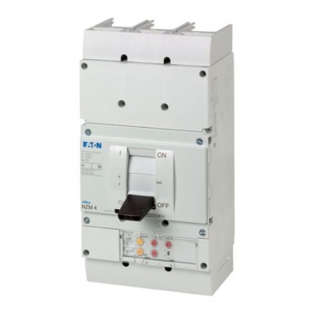
NZMH4-VE1000-S1 290377 Y7-290377 EATON ELECTRIC Circuit-breaker, 3p, 1000A 1000V
NZMH4-VE1000-S1
290377
Y7-290377
EATON - MOELLER
1 Pcs.
Circuit-breaker, 3p, 1000A 1000V
NZMH4-VE1000-S1
Eaton Moeller series NZM - Molded Case Circuit Breaker. Circuit-breaker, 3p, 1000A 1000V, VE1000-S1
Circuit-breaker NZM4, 3 pole, Switching capacity 1000 V 50/60 Hz( Ics): 20 kA, Rated current = rated uninterrupted current( In = Iu): 1000 A, Installation type: Fixed, Screw connection, Standard/Approval: IEC, Protective function: Systems, cable, selectivity and generator protection
Automation > Power circuit-breaker for trafo/generator/installation protection
Circuit Breakers NZM
Product condition, packaging, certifications and applicable manufacturer warranty terms are confirmed with the quotation.
More info
▲General specifications
Product Name
Eaton Moeller series NZM molded case circuit breaker electronic
Catalog Number
290377
Model Code
NZMH4-VE1000-S1
EAN
4015082903770
Product Length/Depth
401 mm
Product Height
207 mm
Product Width
210 mm
Product Weight
21 kg
Compliances
RoHS conform
Certifications
IEC
Product specifications
Type
Circuit breaker
Special features
Amperage Rating
1000 A
Voltage rating
1000 V - 1000 V
Circuit breaker frame type
NZM4
Features
Protection unit
Motor drive optional
Motor drive optional
10.10 Temperature rise
The panel builder is responsible for the temperature rise calculation. Eaton will provide heat dissipation data for the devices.
10.11 Short-circuit rating
Is the panel builder's responsibility. The specifications for the switchgear must be observed.
10.12 Electromagnetic compatibility
Is the panel builder's responsibility. The specifications for the switchgear must be observed.
10.13 Mechanical function
The device meets the requirements, provided the information in the instruction leaflet (IL) is observed.
10.2.2 Corrosion resistance
Meets the product standard's requirements.
10.2.3.1 Verification of thermal stability of enclosures
Meets the product standard's requirements.
10.2.3.2 Verification of resistance of insulating materials to normal heat
Meets the product standard's requirements.
10.2.3.3 Resist. of insul. mat. to abnormal heat/fire by internal elect. effects
Meets the product standard's requirements.
10.2.4 Resistance to ultra-violet (UV) radiation
Meets the product standard's requirements.
10.2.5 Lifting
Does not apply, since the entire switchgear needs to be evaluated.
10.2.6 Mechanical impact
Does not apply, since the entire switchgear needs to be evaluated.
10.2.7 Inscriptions
Meets the product standard's requirements.
10.3 Degree of protection of assemblies
Does not apply, since the entire switchgear needs to be evaluated.
10.4 Clearances and creepage distances
Meets the product standard's requirements.
10.5 Protection against electric shock
Does not apply, since the entire switchgear needs to be evaluated.
10.6 Incorporation of switching devices and components
Does not apply, since the entire switchgear needs to be evaluated.
10.7 Internal electrical circuits and connections
Is the panel builder's responsibility.
10.8 Connections for external conductors
Is the panel builder's responsibility.
10.9.2 Power-frequency electric strength
Is the panel builder's responsibility.
10.9.3 Impulse withstand voltage
Is the panel builder's responsibility.
10.9.4 Testing of enclosures made of insulating material
Is the panel builder's responsibility.
Pollution degree
3
Mounting Method
Built-in device fixed built-in technique
Fixed
Fixed
Equipment heat dissipation, current-dependent
123 W
Utilization category
B
Ambient operating temperature - max
70 °C
Ambient operating temperature - min
-25 °C
Ambient storage temperature - max
70 °C
Ambient storage temperature - min
40 °C
Number of auxiliary contacts (change-over contacts)
0
Number of auxiliary contacts (normally closed contacts)
0
Number of auxiliary contacts (normally open contacts)
0
Degree of protection
IP20
Electrical connection type of main circuit
Screw connection
Lifespan, mechanical
10000 operations
Overvoltage category
III
Number of poles
Three-pole
Terminal capacity (copper strip)
Min. 6 segments of 16 mm x 0.8 mm at flat conductor terminal
Max. 10 segments of 32 mm x 1 mm (2x) at flat conductor terminal
10 segments of 50 mm x 1 mm (2x) at 1-hole module plate
Min. 10 segments of 50 mm x 1 mm (2x) at rear-side connection (punched)
10 segments of 80 mm x 1 mm (2x) at rear-side width extension
Max. 10 segments of 50 mm x 1 mm (2x) at rear-side connection (punched)
Max. 10 segments of 32 mm x 1 mm (2x) at flat conductor terminal
10 segments of 50 mm x 1 mm (2x) at 1-hole module plate
Min. 10 segments of 50 mm x 1 mm (2x) at rear-side connection (punched)
10 segments of 80 mm x 1 mm (2x) at rear-side width extension
Max. 10 segments of 50 mm x 1 mm (2x) at rear-side connection (punched)
Lifespan, electrical
500 operations at 1000 V AC-1
Functions
Systems, cable, selectivity and generator protection
Position of connection for main current circuit
Front side
Rated operational current for specified heat dissipation (In)
1000 A
Release system
Electronic release
Rated short-time withstand current (t = 0.3 s)
19.2 kA
Rated short-time withstand current (t = 1 s)
19.2 kA
Short-circuit release delayed setting - max
10000 A
Short-circuit release delayed setting - min
1000 A
Short-circuit release non-delayed setting - max
12000 A
Short-circuit release non-delayed setting - min
2000 A
Terminal capacity (control cable)
0.75 mm² - 1.5 mm² (2x)
0.75 mm² - 2.5 mm² (1x)
0.75 mm² - 2.5 mm² (1x)
Terminal capacity (copper busbar)
50 mm x 10 mm (2x) at rear-side 2-hole module plate
M10 at rear-side screw connection
Max. 80 mm x 10 mm (2x) direct at switch rear-side connection
Max. 50 mm x 10 mm (2x) direct at switch rear-side connection
Max. 80 mm x 10 mm (2x) at rear-side width extension
Min. 25 mm x 5 mm direct at switch rear-side connection
Max. 50 mm x 10 mm (2x) at rear-side 1-hole module plate
Min. 25 mm x 5 mm at rear-side 1-hole module plate
Min. 60 mm x 10 mm at rear-side width extension
M10 at rear-side screw connection
Max. 80 mm x 10 mm (2x) direct at switch rear-side connection
Max. 50 mm x 10 mm (2x) direct at switch rear-side connection
Max. 80 mm x 10 mm (2x) at rear-side width extension
Min. 25 mm x 5 mm direct at switch rear-side connection
Max. 50 mm x 10 mm (2x) at rear-side 1-hole module plate
Min. 25 mm x 5 mm at rear-side 1-hole module plate
Min. 60 mm x 10 mm at rear-side width extension
Terminal capacity (copper solid conductor/cable)
70 mm² - 185 mm² (2x) at rear-side 1-hole module plate
70 mm² - 240 mm² (6x) at rear-side width extension
185 mm² - 240 mm² (1x) at rear-side 1-hole module plate
50 mm² - 240 mm² (4x) at 4-hole tunnel terminal
50 mm² (4x) at rear-side 2-hole module plate
35 mm² - 185 mm² (4x) at rear-side 2-hole module plate
240 mm² (2x) at rear-side width extension
70 mm² - 240 mm² (6x) at rear-side width extension
185 mm² - 240 mm² (1x) at rear-side 1-hole module plate
50 mm² - 240 mm² (4x) at 4-hole tunnel terminal
50 mm² (4x) at rear-side 2-hole module plate
35 mm² - 185 mm² (4x) at rear-side 2-hole module plate
240 mm² (2x) at rear-side width extension
Terminal capacity (aluminum stranded conductor/cable)
50 mm² - 240 mm² (4x) at 4-hole tunnel terminal
Handle type
Rocker lever
Short delay current setting (Isd) - max
1000 A
Short delay current setting (Isd) - min
1000 A
Instantaneous current setting (Ii) - max
12000 A
Instantaneous current setting (Ii) - min
2000 A
Number of operations per hour - max
60
Overload current setting (Ir) - max
1000 A
Overload current setting (Ir) - min
500 A
Rated short-circuit breaking capacity Ics (IEC/EN 60947) at 1000 V, 50/60 Hz
15 kA
Rated short-circuit breaking capacity Ics (IEC/EN 60947) at 230 V, 50/60 Hz
63 kA
Rated short-circuit breaking capacity Ics (IEC/EN 60947) at 400/415 V, 50/60 Hz
50 kA
Rated short-circuit breaking capacity Ics (IEC/EN 60947) at 440 V, 50/60 Hz
50 kA
Rated short-circuit breaking capacity Ics (IEC/EN 60947) at 525 V, 50/60 Hz
50 kA
Rated short-circuit breaking capacity Ics (IEC/EN 60947) at 690 V, 50/60 Hz
37 kA
Rated short-circuit making capacity Icm at 1000 V, 50/60 Hz
40 kA
Rated short-circuit making capacity Icm at 400/415 V, 50/60 Hz
187 kA
Rated short-circuit making capacity Icm at 440 V, 50/60 Hz
187 kA
Rated short-circuit making capacity Icm at 525 V, 50/60 Hz
143 kA
Rated short-circuit making capacity Icm at 690 V, 50/60 Hz
100 kA
Standard terminals
Screw terminal
Rated short-circuit making capacity Icm at 240 V, 50/60 Hz
275 kA
Rated impulse withstand voltage (Uimp) at auxiliary contacts
6000 V
Rated impulse withstand voltage (Uimp) at main contacts
8000 V
Rated insulation voltage (Ui)
1000 V AC
| Feature Name | Feature Value |
|---|---|
| Rated permanent current Iu (EF001389) | 1000 A |
| Rated voltage (EF003977) | 1000 V |
| Rated short-circuit breaking capacity Icu at 400 V, 50 Hz (EF007048) | 50 kA |
| Overload release current setting (EF002336) | 500 A |
| Adjustment range short-term delayed short-circuit release (EF007129) | 1000 A |
| Adjustment range undelayed short-circuit release (EF007131) | 2000 A |
| Device construction (EF008240) | Built-in device fixed built-in technique |
| Integrated earth fault protection (EF007296) | No |
| Type of electrical connection of main circuit (EF006819) | Screw connection |
| Suitable for DIN rail (top hat rail) mounting (EF007250) | No |
| DIN rail (top hat rail) mounting optional (EF008904) | No |
| Number of auxiliary contacts as normally closed contact (EF001377) | 0 |
| Number of auxiliary contacts as normally open contact (EF001376) | 0 |
| Number of auxiliary contacts as change-over contact (EF003531) | 0 |
| With switched-off indicator (EF007006) | No |
| With integrated under voltage release (EF001390) | No |
| Number of poles (EF001391) | 3 |
| Position of connection for main current circuit (EF006671) | Front |
| Type of control element (EF006976) | Rocker lever |
| Complete device with protection unit (EF008906) | Yes |
| Motor drive integrated (EF006697) | No |
| Motor drive optional (EF007386) | Yes |
| Degree of protection (IP) (EF005474) | IP20 |